///

Ankle replacement-Revision using Wright Invision Ankle replacement system

Learn the Ankle replacement-Revision using Wright Invision Ankle replacement system surgical technique with step by step instructions on OrthOracle. Our e-learning platform contains high resolution images and a certified CME of the Ankle replacement-Revision using Wright Invision Ankle replacement system surgical procedure.
With increasing numbers of total ankle arthroplasty (TAA) operations being carried out worldwide it can be expected that we are going to encounter more frequent and probably more complex failure situations. Failure of ankle replacements occurs due to a variety of causes and some risks for early failure have been established in the literature, Gadd et al. Over time it can be considered that wear will generate a cytokine response and bone lysis, leading to implant migration and cyst formation. This mode of failure is more frequently seen in certain makes of TAA with the best know example being the now withdrawn AES system which generated massive osteolysis in some series .
The origin of cysts and loosening has been widely debated. Rodriguez et al. (2010) hypothesized that cyst formation may be related to pump action leading to synovial inclusion. However Bonnin et al. (2011) felt that some of the cysts may have evolved from pre-existing arthritic cysts. Jacobs et al. (2006) hypothesized that cyst formation may be related to overwhelming of a local afferent transport mechanism with wear particles, resulting in an accumulation of wear particles in periprosthetic tissue. Finally repeatedly authors have failed to find significant wear particles in retrieval specimens from the cysts but some (Koivu et al) have found that there is a switching on of an inflammatory cascade concluding that there is an increased expression of ‘high-mobility group box 1’ receptor for advanced glycation end product and other ‘danger signals’ which could contribute to inflammation around the implants, multilocular cyst formation, and osteolysis in failed TAA implants
The Mobility TAA (DePuy) was launched in 2003 and was withdrawn in June 2014 . There have been no widespread publications of osteolysis though persistent medial pain is reported in some patients.
For failed TAA the commonest option is to convert the arthroplasty to an arthrodesis, which is an accepted and successful technique. Bone graft is often used from the fibula, iliac crest, allograft or using bone substitutes to fill the resulting bone void from where the implant has been removed. If union occurs then pain relief will usually follow, but so does stiffness. If the bone loss is significant then the subtalar joint will often also be sacrificed with even greater loss of motion and functional deficit. Preservation of the subtalar joint is technically possible, usually requiring grafting of the talar defect and plate fixation of the ankle joint, if enough talar bone stock remains.
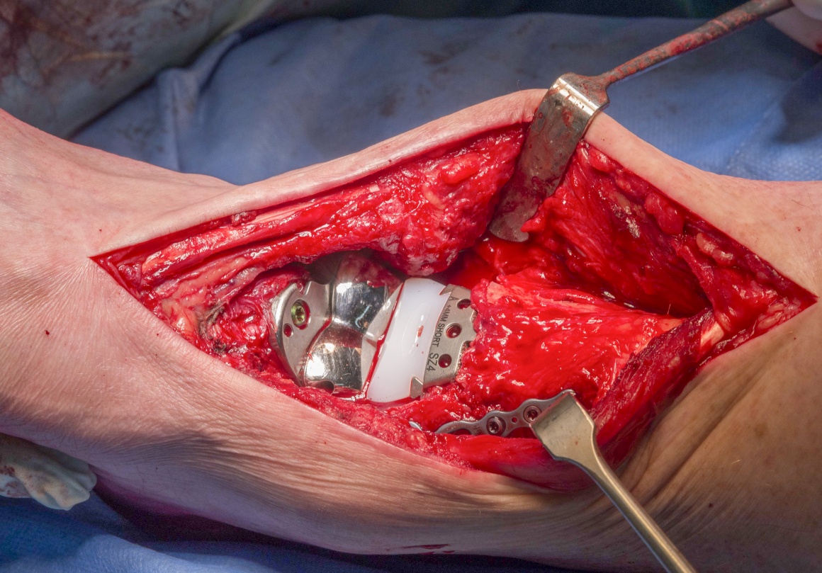
The alternative, in order to preserve motion, is to convert the failed arthroplasty to a revision joint replacement. Specific equipment has now come on to the market to facilitate this. The most tried and tested of these is the InBone system from Wright Medical Technologies, USA. There are publications that support its efficacy at early follow up (Devries, et al). The InBone is a fixed point, jig driven system using image intensification throughout in order to position the revision replacement in a reliable orientation. The system has been added to in the InVision System which also gives metallic solutions to bone loss by use of bulkier tibial trays and talar domes and with the addition of a flat plate to the talus, allowing bridging of cyst defects in the talus. The plate has augments which can be added to the plantar talar surface, though they are limited by their position.
Detailed is a complex revision of a Mobile bearing De Puy Mobility Total Ankle Arthroplasty (which failed due to cyst formation) revised to a fixed bearing InVision Ankle replacement. The case is complicated by bony deficiency of the talus and fracture of the medial malleolus both of which are treated and discussed.
Gadd RJ, Barwick TW, Paling E, Davies MB, Blundell CM. Assessment of a three-grade classification of complications in total ankle replacement. Foot Ankle Int. 2014;35(5):434-437.
Kokkonen A, Ikavalko M, Tiihonen R, et al. High rate of osteolytic lesions in medium-term followup after the AES total ankle replacement. Foot Ankle Int. 2011 Feb;32(2):168-75.
Author : Mr Chris Blundell FRCS (Tr & Orth)
Institution :The Northern general hospital ,Sheffield ,UK.
Clinicians should seek clarification on whether any implant demonstrated is licensed for use in their own country.
In the USA contact: fda.gov
In the UK contact: gov.uk
In the EU contact: ema.europa.e

INDICATIONS
Ankle replacements which initally provide good range of motion and pain relief may later start to fail. This is indicated by increasing pain and/or the presence of loosening or cysts on plain radiographs. This asymptomatic loosing or cyst formation is of concern to those conducting TAA as part of their practice. I would encourage the long term regular review of patients clinically and with radiographs to spot problems early.

SYMPTOMS & EXAMINATION
Patients may demonstrate swelling which is new and pain which may initially be intermittent but gradually becomes more persistent. The pain may be poorly localised. It is important to take a full history especially focussing on any history of poor wound healing after the index procedure which might raise concern about the possibility of low grade sepsis. Blood tests to help exclude this will include a white cell count (WCC) , C reactive protein (CRP) assay and eosinophil sedimentation rate (ESR). Elevation of any of these will raise further concern which will lead to a biopsy to look for infecting organisms. If present then a revision to fusion as a two stage procedure is recommended rather than to a further TAA which is contraindicated.
IMAGING
Plain radiographs as AP and lateral images are the mainstay and are used to provide image surveillance of TAA. Plain radiographs should be examined for implant migration, loosening and cysts. Certain models of ankle replacement have a high incidence of mobile bearing failure, such as the STAR system, and for this reason metal markers are put in the radiolucent polyethylene bearings, these should remain orthogonal and not show any motion year on year.
If the patient has symptoms as described above then a CT scan should be done. This will characterise any areas of poor integration and the all important presence of cysts which may be very difficult see on plain imaging. If sepsis is suspected then SPECT CT has gained popularity but beware that theses images will show increased activity for at least a year post index operation due to healing occurring at the implant bone interface.

ALTERNATIVE OPERATIVE TREATMENT
Cysts may be treated by curettage and grafting with autologous bone or bone substitutes. There are publications supporting this treatment but in the authors experience these cysts tend to reoccur. Gross et al from Duke University examined a series of grafted cysts with 90% good result at 24 months but this fell to 60% at 4 years. If the cysts are in such a position that the structural support of the implant is at risk then even if asymptomatic I will suggest to the patient that these cysts should undergo debridement. I have treated them with installation of bone cement particularly in the lower demand individual.
NON-OPERATIVE MANAGEMENT
Observation of the cysts may be reasonable to see if there is progress in terms of size. Once seen, the cysts do cause concern and radiographic surveillance is mandatory. I do this with the use of CT scans as the assessment is more accurate. Progressive cysts lead me to consider intervention using shared decision making with the patient who may be asymptomatic and so this conversation can be a difficult one.
CONTRAINDICATIONS
The presence of sepsis as discussed above is a complete contraindication to revision TAA. If after CT the cysts are just too extensive or bone loss too great then I would advocate a revision to a fusion with appropriate use of bone graft.
This 68 year old male who is a keen golfer, had had a successful Mobility mobile bearing total ankle replacement 10 years ago for primary ankle osteoarthritis. A cyst had been noted for the previous 18 months without symptoms. In the last 3 months there has been increasingly severe pain and loss of mobility. Plain radiographs show the cyst and its progressive nature. CT scans were performed to gather further information regarding the cyst. The increasing pain is suspicious for the talus neck having become incompetent mechanically or being frankly fractured.

A full discussion with the patient including the risks of continuing to watch and wait or to intervene. Intervention could take the form of packing the cyst or revision to a fusion or a further TAR. The later option was deemed preferable by both patient and surgeon as discussed above.

The patient is positioned supine. Analgesia was in the form of a general anaesthetic with an epidural for pain relief – the duration of the procedure was difficult to define and so a spinal / epidural was not felt to be ideal.
No antibiotics were given on induction until specimens of the cyst had been taken. Although infection was deemed to be very unlikely I did not want to obscure the value for specimens of both the cyst and the implant interfaces that were subsequently acquired.
A thigh tourniquet is used but not inflated at the outset to conserve tourniquet time for a potentially protracted operation
Draping must expose the knee to ensure rotational alignment is respected. The old wound is marked and can be used for the revision TAR.

The pre-operative plain X-ray, hinting at a significant cyst associated with the talar component.

The pre-operative coronal CT confirming the extensive nature of the talar cyst.

The saggital slices in keeping with the coronals.

The sterile Invision Jig was built on a side table according to the manufacturers instructions to facilitate accurate positioning of the limb with 2 planar orthogonal image intensifier guidance (1). The jig needs to be carefully constructed and the alignment of the guides will have already been checked by the manufacturers team in the preceding few days prior to sterilisation.
The jig is built whilst the patient is being anaesthetised and takes around 20 minutes.
It is my practice to ensure that all the equipment is sterile and the wraps have not been damaged prior to the anaesthetist starting any invasive procedures as sometimes the drapes can have tears in them thus we are unable to confirm the kit is sterile and the procedure has been abandoned.

The anterior cutting jig is also assembled

The previous incision is marked and subsequently used.

In every case the leg is prepped to the knee to allow accurate on-table alignment of the prosthesis.

I prefer to operate on cases such as this which may take a long time without a tournquet inflated. The thigh tourniquet is applied in case it needs to be inflated for parts of the procedure which in my experience is more often the start of the operation, when the old implant is being located and scarring is encountered. In this case the tourniquet was never inflated.
Great care is needed with the soft tissues as the anterior neurovascular bundle is often buried in scar tissue. Self retaining retractors are to be avoided throughout due the risk of causing damage to the skin edges and subsequent impaired wound healing.

Careful dissection of the anterior capsule to reveal the polythene bearing which is removed whole with Kochers.
Infection should always be considered and blood tests done pre-operatively. However even in the presence of normal blood inflammatory markers indolent infection may be present and only deep specimens will be able to exclude this. A total of 5 samples are sent for culture and sensitivity. I take one from the anterior capsule and one bone sample from each of the metallic/bone interfaces (ie tibia and talus) once theses components have been removed. Two further soft tissue samples are taken from each side of the joint. 5 are used so that there is never an even mix of ‘growth’ and ‘no growth’ samples there by confirming or refuting infection is clearer. This is the same technique used by hip and knee revision surgeons. The bone and soft tissue can look remarkably normal when low virulence organisms are present.

Bony growth around the talus is removed with osteotomes especially laterally. Care is taken not to damage the medial talus wall around the cyst. The cyst is carefully found before the talar component is removed so as to avoid the risk of fracturing the talus if the metallic component needs to be levered out if there has been bone ongrowth onto its backside.

The talar component is removed using osteotomes to free it up from the underlying bone. A knowledge of the undersurface shape of the talar component is really helpful to allow careful gradual bony dissection to get the component out. I don’t want to remove more bone that needed but equally I do not want to have to remove the component with too much force and thereby risk pulling out lots of native talus bone or risking a fracture. In this case the talus came out moderately easily once the undersurface had been mostly freed up. Inspection of the backside reveals some bony ingrowth.

Specimens of the interface are also now sent for culture. A total of five specimens should be sent to confirm or refute infection.

The tibial component which was loose is tapped into the void created by removal of the talar component and the meniscal bearing and an anterior tibial window is then created to allow for the stem to be removed. By tapping the component distally this window size is minimised thus preserving bone stock. It is common on the Mobility ankle system in my opinion to find the tibial component just has membrane grown onto it without evidence of bony ongowth. This may account for the high incidence of medial pain but does make explantation easier. The bone piece used to create the anterior tibial window is kept and may well be put back after the revision has been implanted. I ask the scrub nurse to keep all bone removed in case it is required later in the procedure for grafting the cysts, to provide support as in this case to the tibial window or if all else fails and the procedure is abandoned in favour of a fusion then all bone will be needed to fill the subsequent void.

The tibial component is removed and inspected – little bone ongrowth is seen. The final bone and soft tissue specimens are sent, from the tibial component-bone interface for microbiological culture.

On exploration of the talus cyst and removal of the membrane (A) from within it – the weakness of the talar neck is revealed. Only a shell of medial and inferior talus remains. The talus integrity needs to be enhanced. I think that this loss of integrity is why this patient started to get pain in what had previously been an asymptomatic cyst. In effect he was becoming unstable.

The talus therefore needs to be stabilised and so I plan for this to be done with two Accutrak screws through the head of the talus which is easily visualised. Thought needs to be made about ensuring that the fixation is not too proximal / superficial in the talus to allow subsequent talar plate / implant positioning. The medial cyst is clearly visualised to ensure good position of the Cannulated screws across this void thereby providing further stability.
The small fenestration in the anterior tibial cortex made earlier and used to remove the tibial component can be clearly seen here – A

Lateral image intensifier view shows adequate position of the guide wires. Length is assessed using the extraction measuring device for the screws ensuring the maximum length is selected to provide for maximum talar stability.

The first Accutrak screw is introduced after drilling and countersinking appropriately, the screw can be seen to cross the cyst (A).

The foot plate part of the jig is applied with forefoot blocks adjusted to control forefoot abduction and adduction and two wires into either side of the heel through the jigs ‘heel cups’. These wires are cut short.

The foot plate is now put into the pre-prepared jig and secured with the threaded knobs. The Achilles support is loosened off to allow the limb to sit at 90 degrees at the ‘ankle joint’. The heel can be seen wired to the calcaneus at A

The Achilles support is brought up to the posterior aspect to support the lower leg in the jig. This is to ensure that the tibia does not ‘sag’ relative to the ankle ie that the ankle remains aligned between the tibia and the talus in the sagittal plane. It can be secured with further wires in the tibia proximally. In this case it sat well and securely without this additional step.

Position of the AP and lateral rods is checked with the image intensifier to ensure the ‘gunshot’ sights are perfectly aligned. The jig can be raised or lowered on either side with swabs under it until these views are perfect on the image intensifier. This ensures that all is aligned in the coronal and sagittal planes. The rods must pass up the virtual ‘center’ of the ankle joint and proceed up the center of the tibia on both coronal and sagittal views with the image intensifier. This ensures that when the drill is introduced that it too will be centre on all views. Gun sight views are used to check against parallax.

The ‘gun sights’ can be seen to be incorrectly aligned here in another example case which is a revision of arthrodesis to ankle replacement

……but a small degree of rotation now aligns the sights so that we are safe to proceed.

The hole in the foot plate is marked and an incision with a 15 blade to allow the rod to be positioned and subsequently checked in alignment with the image intensifier. The incision is propagated with scissors to ensure the plantar nerves are swept out of the wound.

Drill is inserted under power using image intensifier to check alignment. This is slowly done in a ‘pecking’ manner to make sure that once the tibia is enetered that that the drill passes centrally and is not directed by any pedistal that may exist around the old stem site. Continuous checking with the image intensifier to make sure this drill passess up the center of the tibia in coronal and saggital planes.

The drill also passes centrally up the tibia – again in this example case.

The pre-assembled anterior cutting block jig is added to the frame.

The anterior jig is brought ‘down’ as close to the ankle as the soft tissues will allow and care taken to ensure that the letters on each side are the same – ie that it is correctly aligned in the frame and not ‘twisted’ down either medially or laterally.

Prior to securing the cutting block, AP and then lateral images are taken to check size and further confirm alignment. The close distal cut to the Accutrak screws in the talus can be seen. The size is determined both on the coronal view as seen here resecting a small amount of tibia but ensuring boney cuts are made but also on the sagittal view as seen next.
The jig is seen to lie perfectly centred relative to the drill tip A and the drill shaft at B. The fins C represent where the new joint line will be.

On the lateral view, saw blades are positioned into the cutting jig to ensure the distal and proximal cuts are correct in terms of minimising bone resection but allowing a sufficient resection for bone growth onto the new implant. Again the close cut to the screws is clearly seen.

The anterior cutting block is secured to the tibia and talus with guide wires. These are introduced under power but with care not to drive them in too far – the image intensifier on lateral view is useful here.

Once secured, the anterior cutting block guides the captive saw to make accurate cuts to the tibia and the talus superiorly. Care is taken to ensure the saw cuts are neither too deep , putting the posterior tendons and neurovascular structures at risk especially medially, nor too shallow to provide for adequate good resections.

Subsequently the anterior cutting jig is removed without disassembling the locking in case it needs to be reapplied for further cuts. The wires put in earlier remain in the cut areas of the tibia and the talus to help view where these cuts have been made.

the set has a ‘corner’ chisel on it which is now employed to clean up the corners of the resection and carefully the boney pieces are removed. Careful inspection of the posterior stuctures and to ensure the posterior part of the ankle is fully debrided of bone.

I use pointed ended ronguers to clear away all scar and capsule posteriorly also.

The lateral image intensifier view shows clear resection levels with no bone left posteriorly and adequate though small level of bone on the talus to accept the Invision Plate

The reaming rod is now introduced and sequential reaming made up the shaft of the tibia. We had sized the implant and the reamer is guided up to ensure that the metaphysis only is reamed – over reaming will render the stem potentially unstable. The reaming rod has a threaded end onto which the cutting heads are attached. These are sized in diameter to ream for the base plate stem and any additional stems required.

The reamer head is held on a specific ‘clip’ and then threaded onto the reamer rod with the rod being turned by hand. The reamer should always be driven clockwise both reaming in and out, to avoid the reamer head unscrewing in the tibia.

Once reamed up the tibia trial is used to ensure that the tibial resection is adequate and to ensure that the cut sized implant is correct on the image intensifier in terms of coverage of the dsital tibia on the coronal and sagittal images.

The trial bearing is put into the tibial component whist stabilising the tibial trail. Then the talus and plate are also now trialled. The plate is introduced and inspected to ensure that this does cover the resected talus surface without excessive overhang. The position of any augments is determined also with the implant trials. In this case the augments would be posterior to where the cyst in fact was and so would add no additional benefit and were not used. This was as was expected on the pre-operative CT scans which showed the cyst anteriorly only.

The genuine tibial component is selected – the stems are introduced on the side table and the component gently impacted into place. Image intensifier is used to ensure it is well seated and aligned.
In this view the screw across the ’empty’ cyst can be clearly visualised A

Trial plate and talus in situ with the genuine tibial component, showing the length of plate needed to cover the cyst. The tibial component can be seen to cover both anterior and posterior tibial cortices too – this is necessary for component stability

Once the plate position has been determined a wire is positioned in the anterior plate trial and the trial removed. This wire determines the plate position. At this stage and before the genuine plate is now introduced the cyst is grafted. Morcellised bone from the resected tibia is impacted into the cyst and mixed with blood this impacted graft in the cyst can be seen on this image (A).

The genuine plate is positioned as can be seen with reference to the wire. Fixing points are now used to hold it in place. The most distal screw can be seen here. The male part of the morse taper on the plate can be seen (A).

Only the anterior fixation can be reliably used as the posterior screws may enter into the posterior facet of the subtalar joint (A). In my experience great care must be taken to screen with the image intensifier in the lateral view to avoid this. In this case only one posterior screw could be safely used.

The talar component is positioned carefully to ensure the morse taper will engage…..

…..and the talar component is then impacted into place with several firm strikes using the specific impactor. It can seen to rest in close apposition to the plate once it is down.

The genuine ultra-high molecular weight polyethylene (UHMWPE) bearing reflecting the size that had been trialled is now ‘thumbed’ into place. In the case of the InBone and the Invision systems the bearing is a fixed bearing as opposed to a mobile bearing. Although there is an instrument for introducing this in my opinion it is cumbersome and no safer than my thumbs for this purpose.

Final introduction is with careful and gentle taps on the instrument designed for this purpose. Care must be taken not to dislodge the tibial component at this stage, now the tibial component is stabilised with the screw in rod anteriorly (A). Great force is not required to seat the mensicus into place.

All three components are in place. Unfortunately at this stage I was aware on close inspection that there had been an intra-operative fracture of the medial malleolus. This not rare especially in revision situations and in those where there was already a cyst in the medial malleolus. This must be addressed however to avoid instability or risk malalignment as we know that addressing this complication intra-operatively reduces the risk of late implant failure according to Gadd, Barwick et al. (see results papers).

In the presence of a stem I prefer to use a locking plate (A), with or without a supplemental screw. The positioning of these is relatively easy under direct vision and with the assistance of the image intensifier. I use a small Zimmer Biomet Midfoot locking plate which offers very good stability.

On this view the locking plate (A) can be seen along with a supplemental screw (B). In fact one of the drill bits broke and so also is seen – clearly a long and complex case!

The lateral view show the implant and medial fixation to be in a satisfactory position. Note the position of the screws in the talar plate also.

Careful layered closure with attention to the retinaculum which I close with interupted vicryl ‘safety’ sutures – ie not a continuous closure in case this gives way. Skin is closed with nylon interupted sutures with minimum tension.
I dress the wound with vasoline gauze, and orthogauze. A well padded backslab is applied for two weeks.

AP view showing components well aligned and medial malleolus uniting.

Lateral view showing components well aligned and subtalar joint free.

The patient is rested with the limb elevated for two weeks. I use a factor 10a inhibitor (Rivaroxaban) for thromboprophylaxis as per our risk assessment. The patient takes this every day for 6 weeks for revisions such as this where the surgical time is greater than 90 minutes.
The plaster backslab and sutures are removed at 2 weeks and the patient then starts physiotherapy active and passive range of motion rehabilitation. Full weight bearing mobilisation is permitted in a removable walker boot.
The boot is used until the patient is 6 weeks post op and at that stage a further review with an Xray is carried out. After this full and free mobilisation though often a compression sock is used to help reduce swelling. In this case radiographs at 6 weeks show the medial malleolar fracture to have lots of bridging callus.
Physiotherapy continues for 3 to 6 months.

Gadd RJ, Barwick TW, Paling E, Davies MB, Blundell CM.
Assessment of a three-grade classification of complications in total ankle replacement.
Foot Ankle Int. 2014;35(5):434-437
The authors review a 15 year experience of TAA in one centre, reviewing a 17% failure rate at 15 years in 217 replacements over this period. They retrospectively look at complications and their association with failure. Complications are characterised as high grade >50% risk (deep sepsis, aseptic loosening, implant failure) or low grade <50% risk (Malleolar fractures, wound healing problems, technical malposition) for failure leading to revision to further TAA or arthrodesis.

Kokkonen A, Ikavalko M, Tiihonen R, et al.
High rate of osteolytic lesions in medium-term followup after the AES total ankle replacement.
Foot Ankle Int. 2011 Feb;32(2):168-75.
A two year review demonstrated 79% survival of 38 implants but with 50% showing osteolysis and 24% having large cysts and massive osteolysis at this early stage. The implant was abandoned by the authors because of these concerns.
Koivu H, Takakubo Y, Mackiewicz Z, Al-Samadi A, Soininen A, Peled N, Kukis M, Trokovic N, Konttinen YT.
Autoinflammation around AES Total Ankle Replacement Implants.
Foot Ankle Int. 2015 Dec;36(12):1455-62
A complex paper to read but interesting pathology science around retrieval specimens from cysts in AES implants. The authors go on to characterise certain receptors in these specimens and postulate a mechanism for cyst formation due to an inflammatory mechanism.
Gross CE, Huh J, Green C, Shah S, DeOrio JK, Easley M, Nunley JA.
Outcomes of Bone Grafting of Bone Cysts After Total Ankle Arthroplasty.
Foot Ankle Int 2016 Feb; 37(2):157-164
The authors located cysts in 31 cases on review of more than 700 TAR. Cysts were treated in a variety of methods including autograft, allograft, synthetic material, PRP and cement. Patients images were reviewed at 24 and 48 months. The authors draw no specific advice as to which technique is best for treatment nor have they given specifics as to why the variety of techniques was employed. They have reported cyst fill rates of 90% at 2 years review falling to 60% at 48 months. 2 cases had more tan one surgeries for the same cysts. 4 cases had failed before 2 years with these cases requiring component revision or in one case TTC fusion.
A complex paper to read but interesting pathology science around retrieval specimens from cysts in AES implants. The authors go on to characterise certain receptors in these specimens and postulate a mechanism for cyst formation due to an inflammatory mechanism.
Gross CE, Huh J, Green C, Shah S, DeOrio JK, Easley M, Nunley JA.
Outcomes of Bone Grafting of Bone Cysts After Total Ankle Arthroplasty.
Foot Ankle Int 2016 Feb; 37(2):157-164


Reference

  • orthoracle.com
Dark mode powered by Night Eye