
Learn the Ankle replacement-Wright Prophecy surgical technique with step by step instructions on OrthOracle. Our e-learning platform contains high resolution images and a certified CME of the Ankle replacement-Wright Prophecy surgical procedure.
Customised Patient Specific Instrumented ankle replacements are the latest advance in this emerging field.
The first ankle replacement was implanted in 1970 by Lord & Marotte. It was effectively an upside down hip stem and naturally the results were poor. Since that time there have been several generations of implants. Initially the implants were constrained and cemented, later followed by unconstrained using a mobile bearing meniscal implant and the most modern of implants are now two component fixed bearing.
Ankle replacement technology is an emerging but rapidly growing field. Approximately 900 ankle replacements are performed in the UK each year, in comparison to perhaps 2000 ankle fusions (NJR and HES Data).
The basic premise for ankle replacement technology is based on a lack of understanding how the joint actually works. Initial concepts that the joint is a monoaxial hinge are of course incorrect. Aside from just plantarflexion and dorsiflexion, the joint rotates, inverts and everts and translates forwards and backwards. Indeed even sagital plane motion is not just in one plane as the arc of motion of the talus on the lateral side is greater than the medial side hence creating a rotatory motion within the mortise by the frustrum shaped talus.
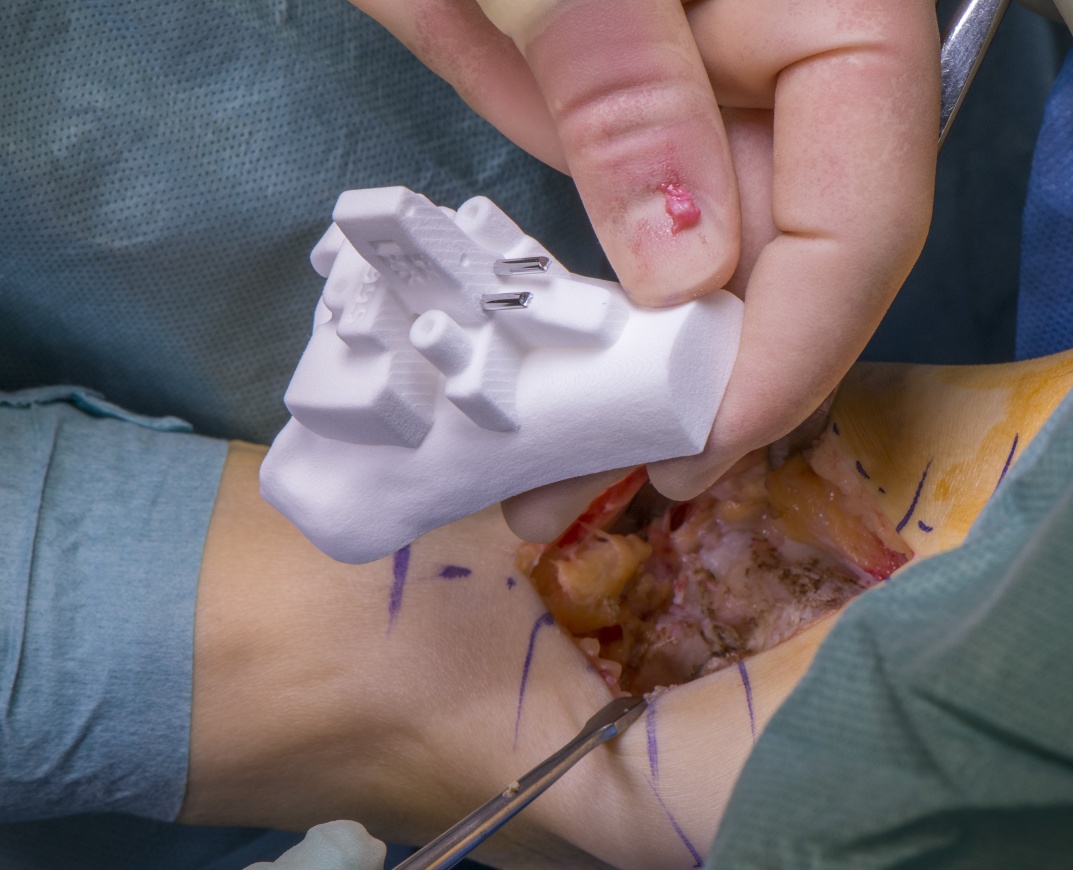
Modern thinking and newer generations of implants have removed the need for cement, using porous coatings or HA coatings for osseointegration, ultra high moleccular weight polyethylene (UHMWPE) as an articulating surface, and better instrumentation. Most implants use cobalt chromium allow although some implants are made also of titanium. The most recent innovation was the use of patient specific instrumentation (PSI) which enables CT scan data of the patient to produce patient specific jigs from nylon that can be used to plan the surgery in advance avoiding the need to determine variables such as alignment, size and rotation on table.
The INFINITY™ Total Ankle System is produced by an American company Wright Medical. Several surgeons were brought on to provide a clinical perspective and the resulting replacement has benefitted from the collaboration between themselves and Wrights’ design engineers.
The Infinity ankle consists of a highly polished metal talar dome, a titanium alloy tibial tray, and an UHMWPE bearing surface.
The key features they claim to have introduced are:
Low-Profile tibial implant design
Resurfacing talar component
Fluoroscopic Visualization
Talar Component Interchangeability with other revision implants
Optimized to use PSI preoperative navigation.
The tibial tray design is low profile and has 3 pegs which are angled backwards so that it can be inserted and impacted from the front. It requires the same standard resection depth for all implant sizes. It comes with a standard and long option to allow for optimal AP coverage.
The spacer or meniscus is made of UHMWPE which is fixed into the tibial component. This seems counter intuitive to the European mobile bearing implants where the meniscus is not fixed but instead is mobile between the joint surfaces. However, there are several reasons they have gone for the fixed bearing solution. Firstly, the FDA (the US regulatory body) does not recognise mobile bearing implants but does recognise fixed bearing implants. Second, the evidence to demonstrate a difference in performance between mobile and fixed bearing implants in knees isn’t there and indeed a small non randomised study by surgeons involved in the Salto Implant (Tournier) failed to show any advantages of mobile bearing over fixed bearing menisci.
Obviously, many of the elements of the Infinity’s design had been used before by other implants on the market and the real innovation in my mind was the ability to use PROPHECY PSI to plan and perform the surgery.

INDICATIONS:
There is only one indication for an ankle replacement and that is end stage osteoarthritis of the ankle and failure of non operative measures.
There are of course several causes of end stage ankle OA. The commonest is post traumatic arthritis following a fracture or severe ligamentous disruption. The latency between injury and arthritis can be 25 years or longer. Other causes include rheumatoid arthritis, seronegative arthropathy, haemachromatosis, and haemophilia). Less common is primary osteoarthritis (unlike the knee and hip where this is the commonest cause).
There are several patient characteristics that would lend support for an ankle replacement over the alternative ankle fusion.
Age – patients over 60
Adjacent joint arthritis – patients with stiffness of other joints for example pantalar arthritis, might receive an advantage of having a replacement on top of perhaps a triple fusion to avoid the impact of having a completely stiff construct.
CONTRAINDICATIONS:
Vascular insufficiency
Neurological disease (with severe muscle weakness or Charcot joints)
Poorly controlled diabetes
Poor soft tissue coverage
Avascular necrosis (more than 30% of the talus)
History of or active sepsis
Deformity – traditional dogma (and the literature) suggests that varus or valgus defromity of greater than 15 degrees should not be replaced. That said this not entirely true because most deformity can be managed and corrected intraoperatively. For example a varus ankle may have lateral ligamentous insufficiency but following ligament reconstruction is stable. A severe planovalgus foot might require a triple fusion prior to consideration of an ankle replacement. If you are looking to develop your experience in ankle replacement you should not be replacing patients with deformity at the outset as these cases are complex.
SYMPTOMS & ASSESSMENT:
Pain, stiffness and impact on quality of life are the main symptoms. As with any arthritic condition you want to find out about walking distance, climbing up and down stairs, managing with slopes and uneven surfaces, ability to work, drive and participate in recreational activity and sports. Ankle arthritis typically causes pain on activity, but patients often describe a start up type of pain and some patients have a history of instability but latterly stiffness, which is classical of an unstable ankle that has developed stabilising osteophytes. Most patients are very concerned by swelling and indeed swelling is a symptom that we as doctors interpret disproportionately to patients, namely we arent worrried but they are very concerned by their swollen ankle.
When assessing the patient stand them up and look at their total lower limb alignment in both the coronal and sagital planes. Look for high arches (peekaboo sign); or flat feet. Look at the heel for varus or valgus malalignment. If there is a cavovarus deformity carry out a Coleman Block test to look for a hindfoot driven varus due to a plantar flexed first ray. Assess the gait as well as the motion at the ankle joint and all adjacent joints. Assess stability at the tibiotalar joint and also the subtalar joints. Carry out a careful and full neurovascular assessment.
INVESTIGATION: Standing anteroposterior and lateral radographs should be performed. I routinely also carry out a long leg alignment film to assess the mechanical and anatomic axes. If pathology of the midfoot or Chopart joints is suspected then also carry out a DP and lateral of the foot.
MRI Scans are useful to document the absence or presence of adjacent joint arthritis as well as to assess the soft tissue envelope eg Achilles, peroneals and tibialis anterior and posterior tendons which can also be a problem in ankle arthritis.
For the PROPHECY ankle a CT scan is performed. There is a full protocol available from the company but essentially this involves a scan which includes the knee to assess the mechanical axis of the tibia. This may or may not be reflective of the mechanical axis of the limb, which is why I also obtain a long leg alignment films (as often these two axes can differ in the case of genu valgum or genu varum). The information is uploaded onto a US server and so appropriate data permissions need to be obtained from the patient and from the hospital.
The PROPHECY system produces 3D printed models of the tibia and talar surfaces as well as a report which allows the surgeon to determine the parameters of the surgery and plan ahead. The 3D printed models are sterilised and made on the set during the surgery. The CT scan should ideally be within 3 months of the surgery date to avoid any interim changes in the ankle to be replaced.
OPERATIVE ALTERNATIVES:
The obvious alternative is an arthrodoesis. Arthroscopy has a role in early osteoarthritis. Distraction Arthroplasty (arthodiastasis) is an option but the evidence is controversial. Bony osteotomies around the ankle for correction of alignment have a role in certain indications.
NON-OPERATIVE ALTERNATIVES:
Non operative methods (weight loss, activity modification, ankle braces, and pain killers) must always be tried first.

The preoperative WHO check should confirm the availability of the kit and implants and their sterility. The nature of the operation and the side of surgery should be crosschecked with surgeon patient and theatre staff.
Imaging must be available and displayed in theatre for referencing during the procedure.
Antibiotics are administered at induction and a popliteal and saphenous nerve block are performed under USS control.
The operation is typically performed with the patient supine in the centre of laminar flow theatre under a general anaesthetic. I have the II machine coming in from the contralateral side to the operative side. The screen is on the ipsilateral side close to the patient’s head. A thigh tourniquet is applied and set at 280mmHg. A sandbag is invariably placed under the ipsilateral buttock.
Routine draping is performed above the knee (like a knee replacement). Diathermy and suction should be available. I use an Esmarch just prior to knife incision to maximise the time of surgery and minimise the tourniquet time.
Specific to the PROPHECY system the following steps are important:
Have the report from the manufacturers on display confirming the implant sizes and any items that you need to know about preoperatively such as depth to cut with the saw, presence of deformity, bone cysts etc. You may need additional equipment such as bone graft/substitute; bone anchors (eg for ligament reconstruction); and screws or plating systems (in case of the need to fix a malleolar osteotomy)
Confirm the jigs number and corroborate this as being for the correct patient.


My post op plan is as follows:
Elevate and neurovascular obs – I use a foam elevation pillow from LEDA Orthopaedics which the patients love more than a braun frame as it keeps the knee bent and the tibia parallel with the floor but elevated to heart level.
Thromboprophylaxis – as per your hospital’s protocol. NICE recommends thrombprophylaxis and at our institution that is Tinzaparin 4500 IU od sc until fully mobile.
Initial non weight bearing until the wound is healed.
Once the wound is healed, my weight bearing status depends on adjunct procedures. In this case where an Achilles release was performed I will keep them in plaster for 6 weeks, weight bearing from week 2 to week 6 and then into a walker boot for a further 6 weeks taking it out for physio and when sleeping.
I would see them on the ward round the following morning to ensure the block has worn off and analgesia is optimised.
Analgesia is given as required. Ideally, I like to stop codeine or opiate based medication as quickly as possible to aid bowel motility and psychological recovery.
Physiotherapy should be started preoperatively with a core stability, and a gluteal programme which they can do in bed and throughout their recovery. This then allows a nice transition to work needed on the ankle and foot and gait retraining, which is secondary in my opinion to proximal chain kinetics.
Xrays are taken usually once between 6 weeks and 6 months postoperatively to ensure no change from the preoperative images and otherwise biannually thereafter to look for signs of loosening, heterotopic bone or cyst formation/progression.

In our first 3 years experience we have performed about 150 Prophecy cases with short term positive results. We intend to publish as appropriate.
A systematic review and meta-analysis of modern total ankle replacements (TARs) by Zaidi et al (BJJ 2013) included 58 papers (7942 TARs) showing an overall survivorship of 89% at ten years with an annual failure rate of between 1.2%-1.9% depending on whether the results are reported by the designers or joint registers. The mean American Orthopaedic Foot and Ankle Society score changed from 40 pre-operatively to 80 at a mean follow-up of 8.2 years. Radiolucencies were identified in up to 23% of TARs after a mean of 4.4 years. The mean total range of movement improved from 23° to 34° and confirmed that TAR has a positive impact on patients’ lives, with benefits lasting ten years, as judged by improvement in pain and function, as well as improved gait and increased range of movement. What is clear however, is that the quality of evidence is weak and fraught with biases.
Further papers by Zaidi reported quality metrics for ankle replacement. In a study in which the UK NJR was linked to the Hospital Episode Statistics (HES) database (BMJ Open 2016) it was shown that the 90-day mortality following TAR was 0.13% and 1-year mortality was 0.72% ; no deaths were as a result of PE. The incidence of PE within 90 days following primary TAR was 0.51% and that patients with an Royal College of Surgeons Charlson score greater than zero (this means co-morbidity) were at 13 times greater risk of PE.
A second paper by Zaidi on the same cohort (BMJ 2013) looked at quality metrics for ankle replacement and showed that TAR has a 30-day readmission rate of 2.2%, which is similar to that of knee replacement but lower than that of total hip replacement. It was also shown that 6.6% of patients undergoing primary TAR require a re-operation within 12 months of the index procedure, and that early revision rates are significantly higher in low-volume centres.
There is an NIHR HTA funded RCT comparing ankle replacement against ankle fusion (ISRCTN60672307) called TARVA is underway and 17 centres in the UK are participating. The study will recruit 310 patients over the age of 50 and randomise them between treatments. All patients have a preoperative MRI and are stratified by the presence or absence of adjacent joint arthritis, so that equal numbers of patients with adjacent joint arthritis will be within each group. The study is likely to report in 2020 with ten year data 8 years later.
Reference
- orthoracle.com


