
Learn the Ankle Replacement-BOX total ankle replacement (MatOrtho) surgical technique with step by step instructions on OrthOracle. Our e-learning platform contains high resolution images and a certified CME of the Ankle Replacement-BOX total ankle replacement (MatOrtho) surgical procedure.
Ankle replacement has been available as an intervention for ankle arthritis since the 1970s. The initial implants were engineered on the assumption that the human ankle joint functioned as a true hinge . They were therefore designed only to allow uniplanar movement (plantar and dorsiflexion) and comprised just 2 components which were mechanically linked. The ankle joints they were implanted into however also functioned with a degree of rotation which had to occur at the weakest point in the “mechanism”. Given the robustness of the implanted ankle hinges this transpired to be the implant/joint interface which therefore led invariably to early implant failure.
The next generation of ankle replacements used a 3 component design, in which the Tibial and Talar components were linked by a UHMW polyethylene meniscus which allowed rotation to occur within the joint itself. These ‘mobile-bearing’ prostheses used the congruity of the ‘articulating’ surfaces, to reduce the constrained forces and overcome the high contact stresses resulting in a reduction in polyethylene wear and mechanical loosening of the fixed components. These initial replacements whose results still define what longevity an ankle replacement should attain are the STAR , Beuchal-Pappas and Salto implants. Advancements have been made in the instrumentation and reproducibility of implantation. In general their 10 year survivorships are lower than reported for hip and knee replacements UK National Joint Registry survival rates are now in the region of 80 percent.
Total ankle replacement is generally not be recommended for younger or higher demand patients due to concerns of longevity due to accelerated wear of the implant, the exception being patients with severe poly-articular inflammatory arthropathy.
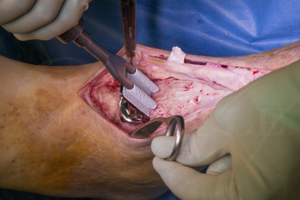
The BOX (Bologna-Oxford) ankle manufactured by MatOrth is a three component prosthesis. The Box ankle replacement prosthesis has been designed to maximise congruency throughout the arc of motion, aiming to mimic normal ankle biomechanics. The bearing surface of the tibial component has a subtle curve in the coronal plane to accommodate for varus/ valgus force through the talo-crural joint. Biomechanical modelling has demonstrated both rolling and sliding motions take place at the talocrural joint. In theory, full congruence should reduce wear by avoiding edge-loading. Similar to the STAR prosthesis, two anchorage bars on the tibial platform of the BOX ankle replacement provide stable primary fixation to the tibial bone. A precisely cut talar component allows a good press fit of the talar component, which is further stabilised with two vertical pegs.
Primary stability of the Box ankle replacement components reduces micromotion assisting the circumstances necessary to provide reliable bone ingrowth.
Readers will also find the following techniques of interest:
Ankle replacement-Revision using Wright Invision Ankle replacement system
Ankle replacement-Wright Infinity ankle replacement
Ankle replacement-Wright Prophecy
Ankle replacement-Star ankle replacement (revision of mensical component)
Ankle Replacement -De Puy Mobility

INDICATIONS
–Isolated Ankle arthritis in a well aligned ankle: Generally a replacement is an operation for the lower demand and fifty plus age group with limited angular deformity and good soft tissue cover around the ankle and with no history of deep infection or neuropathy. With an ankle replacement the failure rate of most implants (which have been in use for long enough) is 2%/annum which equates to a 10 year survivorship of 80%.
A fusion in general is for higher demand/ younger patients or those wishing a greater degree of predictability than afforded by Ankle replacement. With a fusion the “risk” in the majority of patients can be regarded as “front-loaded”. As long as a non-union does not occur (5-10% chance, technique dependent) then in the majority no subsequent / later intervention is likely though the subtalar and midfoot joints are highly likely to become degenerate. Function will reduce with this if this occurs but the lead time is likely to be 10-20 years. .
-Ankle arthritis with deformity : This will self evidently be a more challenging primary operation. Increased failure rates are seen if normal alignment of the limb has not been restored post-operatively. Cases of deformity with bone loss effecting the weight bearing surfaces then cutting the deformity out of the bone may lead to large bony resections .This can produce issues with adequate bony support for the prosthesis and potentially relative laxity of the soft tissues stabilisers . In those ankles with deformity and no bone loss, the soft tissue restraints are likely to be significantly attenuated. The context most often is a varus arthritic ankle where a robust lateral ligament reconstruction may be required at the time of primary operation (such as an Evans peroneal re-routing stabilisation).
Relative indications for ankle replacement (when compared to Ankle Fusion) are also for cases of inflammatory arthropathies involving the ankle, where subtalar and mid foot articulations have (or are more likely to develop) inter-current disease and on one side for a patient with bilateral ankle arthritis.
Increased failure rates are seen if normal alignment of the limb is not restored post-operatively. Consideration should be given to arthrodesis if there is significant deformity at the ankle. Associated procedures may be required to correct hindfoot or proximal limb deformity.
SYMPTOMS & EXAMINATION:
Most patients with severe ankle arthritis localise the pain well to the level of the joint. Very much as with arthritis elsewhere symptoms tend to progress from early activity /start up pain which eases off through to progressively more disabling and continual weight bearing pain and on occasion patients can experience pain at night or at rest. A much less common symptom which can co-exist with pain is that of ankle instability. If gait is becoming altered due to the arthritis pain proximal to the ankle may occur secondary to alteration of the weight-bearing axis of the limb. Some patients complain of swelling which restricts the use of some footwear.
The vast majority of patients will either have a history of a significant injury (such as an ankle fracture), chronic deformity (for example Cavo-varus) or a past history of chronic lateral ligament instability. More rarely the cause is a more generalised tendency to osteoarthritis or an inflammatory arthropathy.
On examination swelling and tenderness well localised to the ankle is common. Range of movement is often reduced and may be uncomfortable. More important than ankle movement is what the subtalar and midfoot mobility is like. If both are very mobile then it is likely that post-fusion good compensatory movement in these joints will allow normal gait and in fitter ,younger patients even the ability to return to running. Conversely if movement here is restricted these joints should be carefully inspected with CT or MRI to identify any arthritic change. If still equivocal then an injection into the ankle joint with inta-articular contrast (see below) is indicated.
Any deformity should be noted. Varus is most common and valgus and equinus less common. The key issues with any deformity are A:Whether it is passively correctable (or not) and B.:Being sure of its anatomical location(s). The former is easily clinically determined .The latter can be more difficult to assess, in particular in the presence of severe deformity and CT and/or long leg alignment films are useful to locate the level of deformity.
Another feature to examine carefully in any varus ankle is the position of the 1st Ray , in particular whether it is plantar or dorsi-flexed and fixed. If this becomes apparent with the ankle corrected to neutral then the first ray will need correcting as part of the procedure.
In assessing equinus it should be appreciated at what level(s) the deformity rests. Beware of associated fixed midfoot equinus which will leave the mid/forefoot in a plantar flexed position once the ankle is fused in neutral if it is ignored. If dealing with isolated ankle equinus, a Silverskiold test will identify whether this is related to gastrocnemius or generalised calf tightness, be prepared to add a triple cut (or open )Achilles release or an isolated gastrocnemius release dependent on the severity of the deformity.
The rest of the lower limbs alignment should not be forgotten. In general correction of deformity should start proximally and proceed distally.
A vascular examination must be made and if abnormal dealt with appropriately.
INVESTIGATION:
Weight-Bearing Plain X-Ray: This is the initial imaging for most patients with ankle arthritis of any degree. Though the ankle is relatively well visualised, the subtalar and midfoot joints aren’t included, in the presence of associated deformity weight-bearing foot X-Rays should be acquired.
CT scan. This is better in defining how much relevant arthritic change exists and where it is than MRI. It is also easier to differentiate the level of deformity from CT than MRI. There are cases where there are significant subchondral cysts which may require bone grafting, or if very large present a contra-indication to surgery. the location and extent is again best defined with CT.
MRI scan: An MRI is more sensitive for early degenerative change but will be degraded by any internal fixation and is not 100% sensitive for early arthritis. It can be more difficult to be objective about the severity of more advanced arthritic change as bone oedema ( a reversible phenomenum) complicates the MRI images. A CT lacks this sensitivity which is a positive and not a negative. Some surgeons prefer to use MRI rather than CT pre-fusion as imaging.
X-Ray guided injection: This should be into whichever joint (ankle or subtalar ) appears more likely the location of symptoms. Contrast is needed as in a proportion of patients the two joints will inter-connect and improvement of symptoms after injection into one cannot under these circumstances be regarded as discriminatory.
ALTERNATE OPERATIVE MANAGEMENT:
Ankle fusion: Can be performed open or arthroscopically, pain levels are lower with the arthroscopic technique and hospital stay in half of patients is just one night. Ultimately no longer term difference with a successful Arthroscopic versus Open ankle fusion , just more patients get there arthroscopically and the journey is easier. In the presence of severe and fixed deformity however it should be the procedure of choice.
Arthroscopic Ankle debridement: This has a role for the treatment of those with lesser degrees of arthritic change & “intermediate” symptoms. There are no clear criteria for this but patients with severe levels of pain on minor activity and possibly at rest or night are unlikely to be appropriate candidates for joint sparing surgery.
Distal Tibial osteotomy: In the much smaller subgroup of patients with isolated arthritis in association with significant distal tibial deformity, where there is a large area of well preserved talo-crural joint, a closing or opening wedge tibial osteotomy can be considered.
NON-OPERATIVE MANAGEMENT:
Activity modification and analgesia.
Local anaesthetic & steroid injection.
Orthotics & Shoewear modifications.
CONTRAINDICATIONS:
Active infection, active smoking, poor vascular inflow: require correction before replacement is considered.
Osteonecrosis, large subchondral cysts, very high body mass index.

The theatre team should confirm that the implants and instruments are sterile prior to anaesthetic commencing.
AP and lateral weight bearing radiographs should be displayed, with alignment views if necessary.
The procedure is done under a general or spinal anaesthetic in combination with a popliteal regional nerve block.
The patient is positioned supine on the operation table.
The side and procedure should be confirmed as part of the WHO check.
Pre-operative antibiotics are administered intravenously.
A sandbag is placed under the ipsilateral buttock so that the 2nd ray is aligned vertically.
The leg is exsanguinated and a thigh tourniquet inflated just prior to skin preparation.
The skin is prepared up to the tourniquet and the leg should be draped above the knee.


How much weight bearing allowed early depends upon the quality of the press fit of components and a Surgeons preference. My own is to limit all weight-bearing for 2 weeks with a light weight cast. Weight bearing in a below cast as pain allows for 2-4 weeks, this allows the soft tissue inflammation to settle, and does not have the disastrous effect upon range of movement (or indeed I think any effect) that one would expect if treating a knee replacement in a similar fashion. from 4(6)-12 weeks mobilisation fully weight-bearing in a pneumatic boot working on active and passive range of movement. The incidence of early post-operative peri-articular fracture is significantly reduced.
Range of movement can be worked upon once anterior wound has healed.
Post operative follow up xrays weeks 6,12 and annually.
Follow up is advised longer term follow up has shown that with all total ankle replacements, there is an incidence of cyst formation and aseptic loosening, these maybe managed early with bone grafting to potentially increase longevity and prevent presentation with catastrophic failure, as revision surgery, whether to a fusion or a replacement is more successful when there is a reasonably preserved bone-stock.

Giannini et al. CORR. 2010; 468(10): 2746-53
Report 51 BOX ankle replacements in 7 centres. Outcomes were assessed using AOFAS scores and radiographs with minimum 2 year follow up. The mean preoperative AOFAS score of 38.5 increased to a mean of over 75. with a survival rate of 97 percent. They concluded that the BOX provided good short term results with high patient satisfaction and low revision rates, but conceded that longer follow-up studies are needed.
Zaidi et al. Bone Joint J. 2013;95-B:1500–7
Meta-analysis, of over 50 papers providing clinical data on TARs concluded that TAR has a positive impact on patients’ lives with benefits continuing over 10 years. The review included data functional data on a number of prostheses including the BOX Ankle, whose results were comparable with other modern designs.
Affatato et al. J Biomech. 2007; 40: 1871-76
Biomechanical study: BOX Ankle replacements tested in a wear simulator, put through load-motion patterns typical of a replaced ankle. Demonstrated BOX Ankle uniform motion through range, with full conformity maintained between components and produced very low level of wear.
Bianchi et al. JBJS-Br. 2012; 94(6): 793-8
62 BOX TARs overall survival was 91.9% at 4 years. The mean AOFAS score had improved by over 40 points at final follow-up. Single surgeon (not involved in design).
Cenni et al. Foot Ankle Int. 2012; 33(4): 290-300
3D video-fluoroscopic analysis of 12 patients, satisfactory recovery of the natural overall motion at the three anatomical planes at 6 months and maintained at last follow up 3 yrs postoperatively, Restoration of the natural parameters of joint rotation axes.
Sopher, Med Eng Phys 2017, Apr 42.
Total ankle replacement design and positioning affect implant-bone micromotion and bone strains
This study assessed micromotion at the implant bone interface, excessive micromotion is related to early implant failure. They found of the three most commonly used implants at that time, the BOX total ankle replacement demonstrated the lowest level of micromotion. Fixation close to the implant, more than one fixation ‘peg’ were thought to be factors that contributed to stability in the BOX ankle.
UK NJR Data 2017
734 primary total ankle replacements were implanted in the UK in 2017. 14.4% were BOX ankles.
The NJR estimated that the overall cumulative percentage probability of revision surgery was 8.7% at 7 years
Reference
- orthoracle.com


